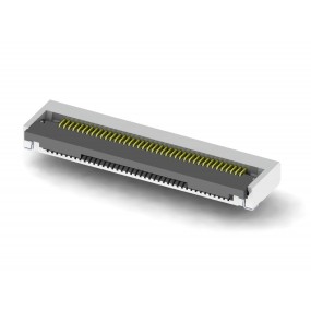
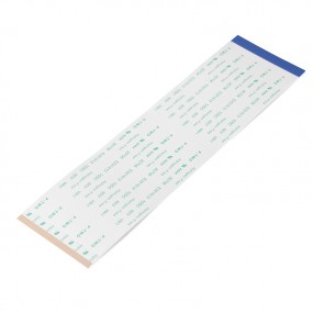
FFC/FPC ZIF connectors are mated with Flexible Flat Cable(FFC) and Flexible Printed Circuit(FPC) . There are various product types ex. flipping & sliding, R/A & V/T, different pitch(0.3~1.0mm), height(0.9mm~) and pin count(4~96pins) can support complex applications and operations. The connectors also can support high speed signal transmission speed and power for visual display, automotive infotainment system and data communication.
For consumer market: LED-LCD TV, Ultra HDTV, Panel, Home theaters, NB, Tablet, DSC/DV, Handheld device, TWS Earbuds, Smart home, IOT module, Gaming machine etc.
For automotive: Car Infotainment, Dashcam, ADAS application etc.
For industrial: POS, KIOSK etc.
1. Different actuator design: front flipping, back flipping and sliding type
2. Internal two side notch or prominent design
3. Impedance matched terminal and grounding pin design
1. Support complex applications and operations
2. Provide contact alignment and increase FFC/FPC retention force
3. Fulfill high frequency / high speed data transmission and better EMI performance
4. Provide flexible mechanical design for customer needs
1. Housing: high temperature thermoplastic UL 94V-0
2. Actuator: high temperature thermoplastic UL 94V-0
3. Contact: copper alloy
4. Fitting nail or ground: stainless steel
5. Contact finish: ive gold plating or matte tin over nickel
6. Fitting nail or ground finish: matte tin over nickel
1. Current rating:
- 1.1 0.3mm pitch: 0.2A/pin
- 1.2 0.5mm pitch: 0.4A or 0.5A/pin
- 1.3 1.0mm pitch: 1.0A/pin
2. Voltage rating:
- 2.1 0.3mm pitch: 30V(AC/DC)
- 2.2 0.5mm pitch: 50V(AC/DC)
- 2.3 1.0mm pitch: 125V(AC/DC)
3. Insulation resistance: 500MΩ min.
4. Dielectric withstanding voltage: 250 or 500VAC
5. Contact resistance:
- 5.1 0.3mm pitch: 100mΩ max.
- 5.2 0.5mm pitch: 30 or 40mΩ max.
- 5.3 1.0mm pitch: 40mΩ max.
1. Temperature range:
- 1.1 -40°C ~ +85°C
- 1.2 -40°C ~ +105°C
2. Humidity: 40±2°C, 90~95%RH for 96hrs
3. Salt spray:
- 3.1 35±2°C, 5±1% density salt for 48hrs
- 3.2 35+1°C/-2°C, 5±1% density salt for 48hrs
1. FFC/FPC retention force:
- 1.1 0.3mm pitch: 15gf/pin Min.
- 1.2 0.5mm pitch: 20 or 30gf/pin Min.
- 1.3 1.0mm pitch: 30gf/pin Min.
2. Durability:
- 2.1 0.3mm pitch: 20cycles
- 2.2 0.5mm pitch: 30cycles
- 2.3 1.0mm pitch: 30cycles
3. Vibration:
- 3.1 1μs max. by MIL-STD-202 method 201
- 3.2 1μs max. by EIA-364-28 condition I
4. Mechanical shock:
- 4.1 1μs max. by MIL-STD-202 method 213
- 4.2 1μs max. by EIA-364-27A condition A
| Product Series | Pitch (mm) | Actuator Type | Product Height (mm) | Mounting Type | Orientation | Contact Position | Soldering Type | Additional GND | Cable Lock Type | Contact Point | Automotive Application |
|---|---|---|---|---|---|---|---|---|---|---|---|
| 196640 | 0.5 | Back Flip | 1.0 | Top-Mount | Right Angle | Top/ Bottom | SMT | Without | Without | Single | NA |
| 196637 | 0.5 | Front Flip | 2.55 | Top-Mount | Right Angle | Bottom | SMT | Without | Without/External Prominence | Dual | NA |
| 196595 | 0.5 | Front Flip | 2.1 | Top-Mount | Right Angle | Bottom | SMT | With | Inner Notch | Dual | NA |
| 196657 | 0.5 | Front Flip | 2.1 | Top-Mount | Right Angle | Bottom | SMT | With | Inner Notch | Dual | NA |
| 196395 | 0.5 | Front Flip | 2.0 | Top-Mount | Right Angle | Bottom | SMT | Without | Without/External Prominence | Single | NA |
| 196033 | 0.5 | Front Flip | 2.0 | Top-Mount | Right Angle | Bottom | SMT | Without | Without | Single/Dual | NA |
| 196225 | 0.5 | Front Flip | 1.8 | Top-Mount | Right Angle | Bottom | SMT | Without | Without/External Prominence | Dual | NA |
| 196415 | 0.5 | Front Flip | 1.75 | Top-Mount | Right Angle | Bottom | SMT | Without | Without/External Prominence | Single | NA |
| 196570 | 0.5 | Front Flip | 1.55 | Top-Mount | Right Angle | Bottom | SMT | Without | Inner Notch | Dual | NA |
| 196479 | 0.5 | Front Flip | 1.5 | Top-Mount | Right Angle | Bottom | SMT | Without | Without | Dual | NA |
| 196490 | 1.0 | Front Flip | 1.0 | Top-Mount | Right Angle | Bottom | SMT | Without | Without | Single | NA |
| 196294 | 0.5 | Front Flip | 0.9 | Top-Mount | Right Angle | Bottom | SMT | Without | Without | Single | NA |
| 196200 | 0.3 | Front Flip | 1.0 | Top-Mount | Right Angle | Bottom | SMT | Without | Without | Single | NA |
| 196439 | 0.3 | Back Flip | 0.9 | Top-Mount | Right Angle | Top/ Bottom | SMT | Without | Without/External Prominence | Single | NA |
| 196533 | 0.3 | Back Flip | 0.9 | Top-Mount | Right Angle | Top/ Bottom | SMT | Without | Without/External Prominence | Single | NA |
| 196508 | 1.0 | Back Flip | 2.7 | Top-Mount | Right Angle | Bottom | SMT | Without | Inner Notch | Single | NA |
| 196047 | 1.0 | Front Flip | 2.0 | Top-Mount | Right Angle | Bottom | SMT | Without | Without | Single | NA |
| 196503 | 1.0 | Front Flip | 1.75 | Top-Mount | Right Angle | Bottom | SMT | Without | Without/External Prominence | Single | NA |
| 196087 | 1.0 | Front Flip | 1.5 | Top-Mount | Right Angle | Bottom | SMT | Without | Without | Single | NA |
| 196356 | 0.5 | Back Flip | 2.5 | Top-Mount | Right Angle | Bottom | SMT | With | Inner Notch | Single | NA |
| 196532 | 0.5 | Back Flip | 2.0 | Top-Mount | Right Angle | Top/ Bottom | SMT | Without | Without | Dual | NA |
| 196433 | 0.5 | Back Flip | 1.8 | Top-Mount | Right Angle | Bottom | SMT | Without | Inner Notch | Dual | NA |
| 196652 | 0.5 | Back Flip | 1.6 | Top-Mount | Right Angle | Bottom | SMT | Without | External Prominence | Dual | NA |
| 196357 | 0.5 | Back Flip | 1.2 | Top-Mount | Right Angle | Top/ Bottom | SMT | Without | Inner Notch | Single | NA |
| 196070 | 0.5 | Front Flip | 2.2 | Top-Mount | Right Angle | Bottom | SMT | Without | Without | Single | NA |
| 196528 | 0.8 | Back Flip | 1.5 | Top-Mount | Right Angle | Top/ Bottom | SMT | Without | Inner Notch | Dual | NA |
| 196579 | 0.8 | Front Flip | 1.2 | Top-Mount | Right Angle | Bottom | SMT | Without | Inner Notch | Single | NA |
| 196415-XX-36 | 0.5 | Front Flip | 1.75 | Top-Mount | Right Angle | Bottom | SMT | Without | Without/External Prominence | Single | Available |
| 196588 | 0.5 | Front Flip | 2.5 | Top-Mount | Right Angle | Bottom | SMT | Without | Inner Notch | Dual | Available |
| 196598 | 0.5 | Front Flip | 2.5 | Top-Mount | Right Angle | Bottom | SMT | With | External Prominence | Single | Available |
| 196542 | 0.5 | Front Flip | 2.55 | Top-Mount | Right Angle | Bottom | SMT | Without | Without/External Prominence | Dual | Available |
| 196541 | 1.0 | Front Flip | 2.0 | Top-Mount | Right Angle | Bottom | SMT | Without | Without | Dual | Available |
| 196564 | 1.0 | Draw | 5.5 | Top-Mount | Vertical | No Designated | SMT | Without | Inner Notch | Dual | Available |